

Motor Controls
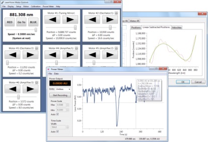 The main tuning software for our systems. It provides automated tuning to a specified wavelength/wavenumber as well as individual control of the optical elements. Many of our customers use LabVIEW™ for their experiments, and the external communication options in Motor Controls allow for existing experiment software to control the system over TCP/UDP and RS-232.
Previously known as MDRIVE, the software was rewritten in 2010 to be work with Windows XP SP2 and higher and is now called Motor Controls. If you are interested in upgrading your system please contact us for assistance.
Features
Precise Motor Control
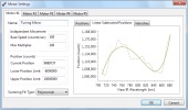
There are two fitting types supported by the program: 9ᵗʰ order polynomial and cubic spline.
External Project Integration
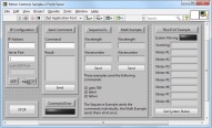
The system can be controlled externally over RS-232 or Ethernet using a library of 14 commands. A sample LabVIEW™ program is provided that demonstrates Ethernet communications with Motor Controls. An Ethernet communications program, MotorSendCmd.exe, is included and can be immediately integrated into any control software or used on its own to test Ethernet communications. The source code for MotorSendCmd.exe is provided in the .c file of the same name and can be used to achieve a more seamless integration into an external control program.
Power Meter Integration
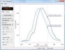
When used with a USB voltmeter from Digital-Measure the program can interface with the analog output from a laser power meter. This allows power data to be viewed and recorded within the program, and more importantly to be associated with the Near-IR output wavelength and motor positions. There are two views for visualizing data: the first is analogous to a chart recorder, the second is a calibration assistant. Data collected in both views is identical and the files generated can be viewed in both. Data is saved as a CSV (comma-separated values) file and can be visualized using the software or in any number of graphing programs.
Etalon Adjust
Note: The Etalon Adjust software is an optional component useful for only a small number of our systems and may not be present in your version.
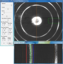
Etalon Adjust uses etalon interference images to automate either adjustment of the OPO/OPA’s main cavity length to maintain single-mode laser operation, or narrow the line-width of unseeded output, depending on the system. In single-mode systems the adjustment is accomplished using a piezo actuator; for unseeded systems a motor is used.
In an etalon image there are two classes of rings: main rings which represent the predominant transverse mode and fringe rings which represent the contribution of other less dominant modes. To determine the appropriate adjustment a rectangular portion of the etalon image is selected where the curvature of the rings is negligible. The pixels in this region are then summed by column and that with the greatest sum is taken to represent a main ring. The region is then examined for fringe rings and an adjustment is made based on the relative fringe intensities with the goal of either eliminating the fringe rings or equalizing their intensities.
Software Documentation
Motor Controls documentation is available in HTML form.
Version History
The following is a list of program versions and a description of the major change between each. Many releases fix minor bugs or include small code improvements. For a complete list of changes please see the release notes.
- 3.5.2.0(November 27, 2020)Fix bug when specifying motor 8 in an external command.
- 3.5.1.2(June 26, 2019)Fit selection bug fix.
- 3.5.0.3(March 2, 2018)New default layout (four-column), TELLPWR bug fix.
- 3.4.3.0(December 12, 2015)Reverted 3.3.0.12 change to timing of RS-232 notification at end of scan to original behavior
- 3.4.2.0(September 26, 2015)Bug Fix: Multiple TCP connections would cause the program to crash
- 3.4.1.3(January 1, 2015)Improved MultiFlex ETH support, integration with system manual, bug fixes.
- 3.4.0.2(May 6, 2014)Support for the MultiFlex ETH motion controller, values displayed and entered in the Go To scanning dialog now match the current wavelength display mode (i.e., MIR), bug fixes.
- 3.3.3.3(October 4, 2013)Optional motor gearhead backlash correction, merged in an improved version of Etalon Adjust, bug fixes.
- 3.3.2.4(February 21, 2013)Spectrum View, TELLPWR command, charts respond to changes in display mode, bug fixes.
- 3.3.1.0(November 16, 2012)Bug Fix: Cubic spline calculation produces incorrect results
- 3.3.0.12(September 21, 2012)Power meter integration, major interface updates.
- 3.2.2.0(April 27, 2012)Added an external command to report the status of motor movement and any scanning operation.
- 3.2.1.0(February 8, 2012)A bug-fix release of 3.2.0.0.
- 3.2.0.0(January 9, 2012)Major changes include the ability to generate fitting files from calibration data within the program as well as the ability to view the currently active fits. Additionally, the cubic spline formula has been updated to produce more accurate curves.
- 3.1.0.0(September 13, 2011)Released as an installer package. Contains a large number of changes, including a demo mode, program settings dialog, and important bug fixes.
- 3.0.4.2b(June 8, 2011)Source diagrams for the LabVIEW™ Ethernet sample .vi's are now provided.
- 3.0.4.2(March 24, 2011)Corrected two serious errors in the cubic-spline fitting routine.
- 3.0.4.1(February 21, 2011)Program is restricted to running only one instance.
- 3.0.4.0(February 4, 2011)Introduced ability to control motor positions while scanning in wavelength using a cubic-spline fit of datapoints, providing improved control of motor #2.
- 3.0.3.0(December 20, 2010)Additional external commands have been added: MOVE, STOP, TELLPOS, and SETSCRL.
- 3.0.2.1(November 11, 2010)Further improvements of Ethernet communications.
- 3.0.2.0(November 7, 2010)Now possible to send more than one system command as a single Ethernet command.
- 3.0.1.0(October 28, 2010)Added ability to add offset from 1064nm.
- 3.0.0.0(October 20, 2010)First release supporting 32-bit Windows.